Knaldtech Start
User Tools
Sidebar
Table of Contents
Specular
The target “Specular” can either be a basic Gaussian blur of the source image or it can be used to represent pre-calculated lighting according to user adjustable surface characteristics (roughness).
Multiple roughness values can be represented by a single cube map with sharp reflections being placed at the top MIP map levels and the most blurry reflections at the bottom MIP map levels.
The Specular Group's Settings
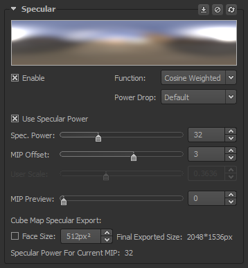
Enable: Enable convolution to generate the Specular map
Function: The type of convolution to be used by Lys for the generation of the Specular map. You can choose between the various functions listed below.
- Cosine Weighted:
- Gaussian:
- GGX:
Power Drop: The ramp used by Lys to dictate the convolution amount on a per MIP basis. You can choose between the various power drops listed below.
- Default: The standard ramp used by Lys. This ramp is the inverse of the one found within Marmoset Toolbag 2 with adjusted constants.
- Log2: A user configurable ramp that allows variable distribution of specular power values across MIP levels.
- Burley: The square root of true roughness (inverted smoothness) distributed across a perceptually linear curve.
Use Specular Power/Use Roughness: Check this to enable Lys to work with specular power rather than roughness & vice versa.
MIP Offset: This value represents an offset from the bottom 1×1 cube map MIP level. The default value of 3 corresponds to assigning a specular power of 1 to level 8×8.
User Scale: User Scale allows you to distribute roughness/specular power values across MIP levels. Generally this is best done after adjusting the MIP Offset control. You can observe the values you get by either toggling through the MIP levels in the specular group or by selecting the roughness view in the 3D Preview.
MIP Preview: This slider controls which MIP level is currently selected and viewable in the 2D Preview.
Cube Map Specular Export: Here you can change various export settings for the Specular Cube map.
Face Size: The selected export size for each face in the Specular Cube map.
Final Exported Size: The final exported size for the completed Specular Cube map when viewed in a vertical or horizontal cross layout consisting of a total of 6 faces.
Roughness/Specular Power For Current MIP: The roughness/specular power value for the currently selected MIP level.
Power Drops Within Lys
Image Based Lighting Sample Shader
In the following we describe how to use cube maps generated with Lys in a shader for image based lighting. We also provide a free, complete IBL sample shader & associated source files.
Please see the Image Based Lighting Sample Shader page for more details.
Computing MIP Levels From Specular Power/Roughness
To compute MIP level from specular power/roughness you need to have the number of MIP levels in the cube map available in your shader.
If you are developing in HLSL then you can get hold of it using GetDimensions() and if you are using GLSL then you can use textureQueryLevels().
If you are developing in a shader language where you do not have access to such built-in functions then it's suggested to pass it as a constant to your shader.
Alternatively you can compute it in shader code using the following function:
int GetNrMips(samplerCube cube_spec)
{
   int top_dim = textureSize(cube_spec, 0).x;
   int nMips = int(log2(float(top_dim>0 ? top_dim : 1)))+1;
   return nMips;
}
Power Drops
In the following, the roughness/specular power drops of Lys will be explained and we describe how to map to the correct floating point MIP entry. Be sure to enable trilinear filtering when using cube maps for image based lighting to achieve continuous roughness.
It has become very common to use “roughness texture maps” to describe the specular reflection of a material. Note that these are not equivalent to actual academic roughness which is defined as the root mean square slope of the profile. Roughness texture maps in computer graphics have for practical reasons been defined as a more even distribution of blurriness. In the following we will refer to the roughness in texture maps as “perceptual roughness” and when we refer to roughness we are referring to academic roughness.
Perceptual roughness, roughness and specular power can all be thought of as different parametrizations for the same parameter and it is possible to convert back and forth. For instance the conversions from roughness to perceptual roughness and back again are:
float RoughnessFromPerceptualRoughness(float fPerceptualRoughness)
{
   return fPerceptualRoughness*fPerceptualRoughness;
}
float PerceptualRoughnessFromRoughness(float fRoughness)
{
   return sqrt(max(0.0,fRoughness));
}
Similarly we can also convert from perceptual roughness to specular power and back again.
float SpecularPowerFromPerceptualRoughness(float fPerceptualRoughness)
{
   float fRoughness = RoughnessFromPerceptualRoughness(fPerceptualRoughness);
   return (2.0/max(FLT_EPSILON, fRoughness*fRoughness))-2.0;
}
float PerceptualRoughnessFromSpecularPower(float fSpecPower)
{
   float fRoughness = sqrt(2.0/(fSpecPower + 2.0));
   return PerceptualRoughnessFromRoughness(fRoughness);
}
Thus we should not think of perceptual roughness as specifically for GGX or specular power as specifically for Blinn-Phong BRDFs. Finally for those using “smoothness texture maps”. These are simply equal to one minus the perceptual roughness and vice versa.
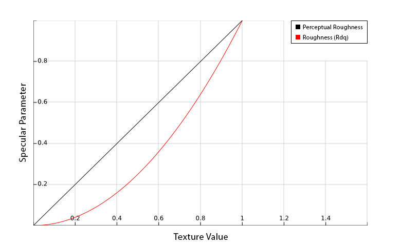
Burley
In Lys we currently support three ways to distribute blurriness across MIP levels. Burley1), Default and Log2.
Burley is the most straight forward and the one we recommend using for image based lighting. The top MIP level will always be used for a 100% sharp reflection (roughness 0.0) and the offset from the bottom MIP level specified using “MIP Offset” in the specular group determines where we have 100% blurriness (roughness 1.0). The default offset of 3 corresponds to MIP level 8×8. Checking “Coarse Irradiance” in the 3D Preview will enable using the MIP level at your chosen offset for diffuse lighting in the viewport.
Note that our implementation of BurleyToMip() below differs from the more typical form as cube maps convolved in Lys are based on RdotL and not NdotH. You can find a more detailed description in Pre-convolved Cube Maps vs Path Tracers.
Despite the difference in distribution of MIPs the lit specular response resulting from the “roughness texture” will be identical to existing PBR based game engines and tools.
float BurleyToMip(float fPerceptualRoughness, int nMips, float NdotR)
{
   float fSpecPower = SpecularPowerFromPerceptualRoughness(fPerceptualRoughness);
   fSpecPower /= (4*max(NdotR, FLT_EPSILON));		// see section "Pre-convolved Cube Maps vs Path Tracers"
   float fScale = PerceptualRoughnessFromSpecularPower(fSpecPower);
   return fScale*(nMips-1-nMipOffset);
}
As we can see this implementation has an intermediate step which is explained in section “Pre-convolved Cube Maps vs Path Tracers”. If this is considered too expensive then a cheaper close alternative is to use the following replacement.
float BurleyToMipSimple(float fPerceptualRoughness, int nMips)
{
   float fScale = fPerceptualRoughness*(1.7 - 0.7*fPerceptualRoughness);    // approximate remap from LdotR based distribution to NdotH
   return fScale*(nMips-1-nMipOffset);
}
The Log2 Power Drop
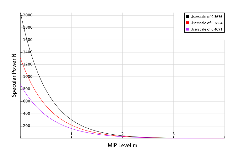
The goal when designing your drop curve is to get a distribution of specular power values across MIP levels that fit the needs of your application. The first thing to do is to decide at which MIP level to place the specular power of 1, which in Lys corresponds to the highest roughness.
You do this by specifying the “MIP Offset” in the specular group. This value represents an offset from the bottom 1×1 cube map MIP level. The default value of 3 corresponds to assigning a specular power of 1 to level 8×8.
Next you need to distribute the remaining specular power values. For the Log2 distribution this is done using the “User Scale”. There are two ways to observe the values you get. One is by toggling through the MIP levels in the specular group. The other is by selecting the roughness view in the 3D Preview.
The code to convert the specular power to a MIP entry is as follows:
float GetSpecPowToMip(float fSpecPower_in, int nMips, float NdotR) // log2 distribution
{
   float fSpecPower = fSpecPower_in / (4*max(NdotR, FLT_EPSILON));  // see section "Pre-convolved Cube Maps vs Path Tracers"
   return (nMips-1-nMipOffset) - log2(fSpecPower)*fUserScale;
}
Ultimately the goal is to pick fUserScale such that you get the distribution you need. But for numerical interpretations you could also think of fUserScale as a change in log-base since log_a(x)=log2(x)/log2(a) which implies fUserScale is 1/log2(a).
Another convenient way of looking at it is you can assign a specific specular power N to a chosen MIP offset from the bottom mMipPivot.
To achieve this we get:
fUserScale = (mMipPivot-nMipOffset)/log2(N)
So for instance to assign a specular power of 2048 to the pivot 7 which corresponds to the MIP map resolution 128×128 we would get 4/11.
Specular Power Distribution across Mip Map Levels
The Default Power Drop
The first power drop “Default” allows the user to pick a maximum specular power/roughness for the top MIP level. The curve we use for this was kindly made available to us by the Marmoset team who use it to convert from a gloss map [0;1] to a specular power inside of Marmoset Toolbag 2.
The Marmoset Toolbag 2 curve is ( -10.0 / log2( gloss*0.968 + 0.03 ) )^2 which gives a specular power range of about 4.0 to 12 Million. In the context of image based lighting this range is a bit more than we need so we adjusted the constants by making them 0.9921 and 0.00098 instead which gives us the output range of 1.0 to 999999.
Since we are going from specular power to MIP level and not the other way around we need to use the inverse function.
We also need to know the user's choice for maximum specular power fUserMaxSPow of the top MIP level.
Finally we can compute the MIP level as:
const float k0 = 0.00098, k1 = 0.9921;

// pass this as a constant for optimization
uniform float g_fMaxT = ( exp2(-10.0/sqrt( fUserMaxSPow )) - k0)/k1;


float GetSpecPowToMip(float fSpecPower_in, int nMips, float NdotR)
{
   float fSpecPower = fSpecPower_in / (4*max(NdotR, FLT_EPSILON));  // see section "Pre-convolved Cube Maps vs Path Tracers"
   // Default curve - Inverse of TB2 curve with adjusted constants
   float fSmulMaxT = ( exp2(-10.0/sqrt( fSpecPower )) - k0)/k1;

   return float(nMips-1-nMipOffset)*(1.0 - clamp( fSmulMaxT/g_fMaxT, 0.0, 1.0 ));
}
Pre-convolved Cube Maps vs Path Tracers
Another detail worth noting is that pre-convolved cube maps have to be made such that the convolution process ignores the orientation of the receiving surface.
If results are compared to path tracers used for movie production quality you will find the result you get from a pre-convolved cube map, for the same specular power, is roughly 4 times more sharp.
The distinction is the path tracer will use the roughness/specular power to drive a formulation based on n_dot_h as opposed to l_dot_r where the normal is arbitrary.
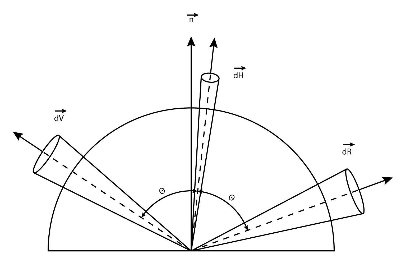
For pre-convolving cube maps we are limited to l_dot_r. However, we can account for the difference in the shader by observing the relation between the solid angle of the half vector dH and the reflection vector dR which is dR = 4 * h_dot_r * dH2).
Reflected Beam
As an approximation we can correlate size of solid angle with “blur strength”and replace h_dot_r with n_dot_r. So ultimately what we do is adjust our specular power in the following way:
fSpecPow /= (4*max(dot(vN, vR), FLT_EPSILON));
This works because the specular power is roughly inversely proportional to the amount of blur.
Note we perform this correction inside the functions GetSpecPowToMip() and BurleyToMip() given above. This adjustment is of course just for the cube maps and should NOT be applied to the specular power used with ordinary lights since for these we simply use an n_dot_h based formulation as opposed to l_dot_r. This approach will work with both normalized Blinn-Phong3) 4) and GGX. In the former case use cosine weighted convolution in Lys. Though it is an approximation it gives results that are close to what the path tracer will provide for the same specular power. The approach will also harden the reflection as we approach the silhouette which is more physically correct.
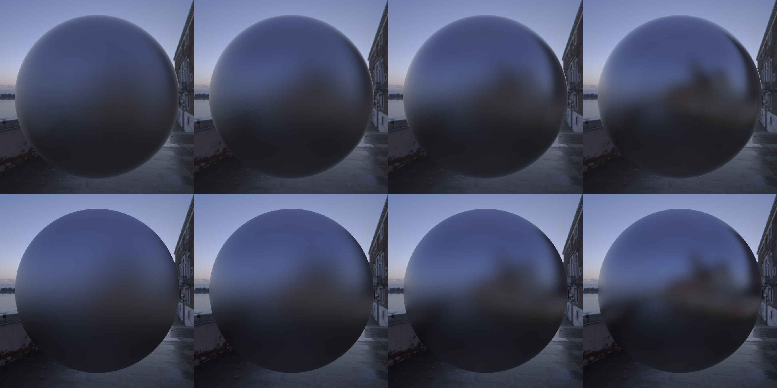
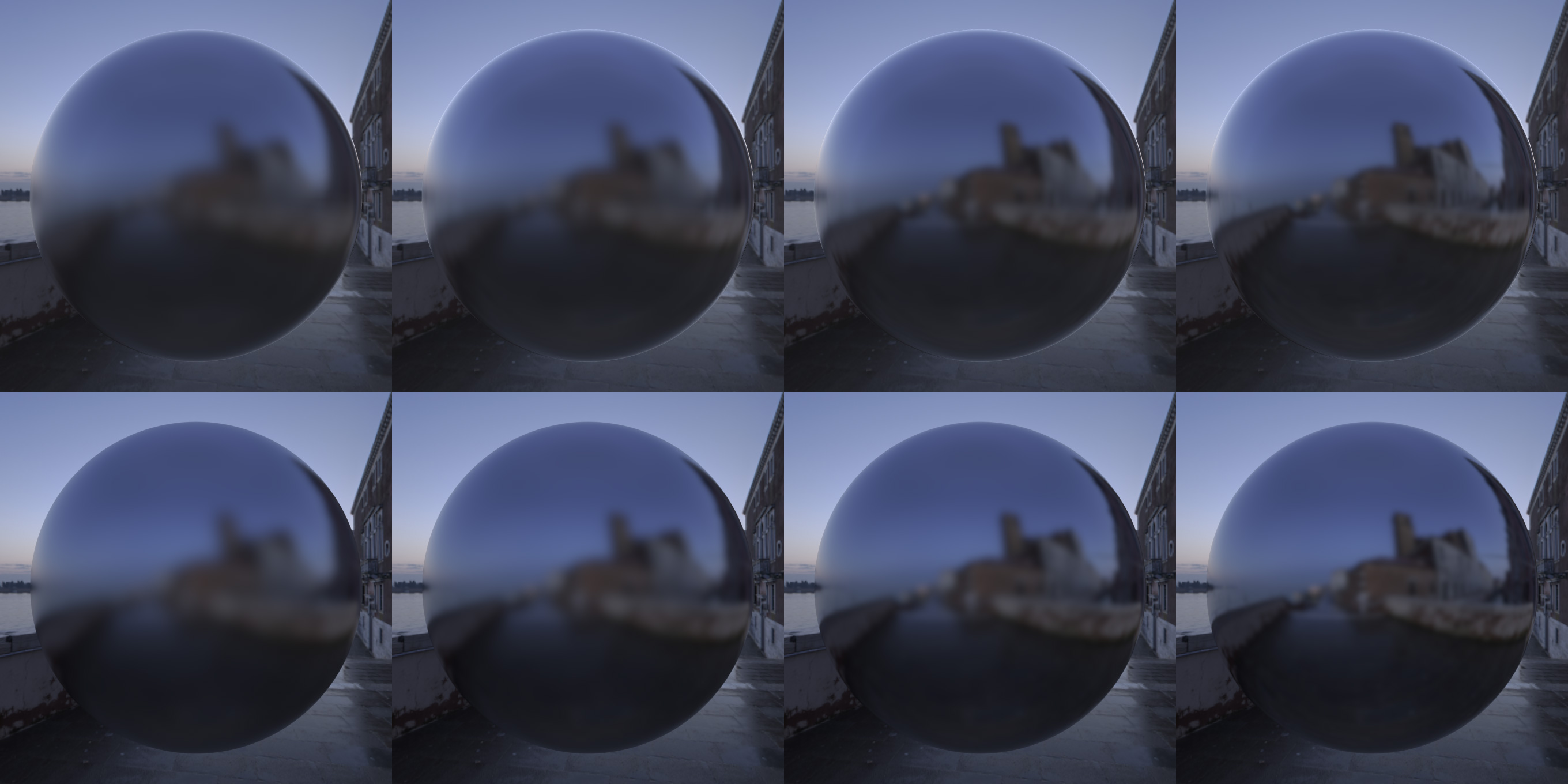
Below we have set out renders5) featuring results of Lys cube maps vs a path tracer with various specular powers/roughness. The results using Lys cube maps are set out in the top row of each image whereas the bottom row shows the results from the path tracer.
As we see using the approach described above we achieve matching results to a path tracer. The “blur strength” matches when the same specular power is used and notice how the reflection of the building on the right side hardens as we approach the silhouette of the sphere. Traditionally this requires half vector based BRDF formulations which cannot be precomputed and stored in the cube map.

